How to Install Multi-Part Access Covers and Frames
Multi-part access covers, also called multi-span or beamed covers, close pit clear openings too large for a single cover by combining standard ductile iron covers in rows carried on removable I-beams. How well a multi-part system performs in service depends as much on installation as on manufacture: the frame is designed to be fully supported by concrete, and the machined cover-to-frame fit is deliberately tight so the finished unit is non-rocking and resists water ingress.
This guide sets out R&B UK’s recommended installation sequence for solid top and concrete infill slide-out multi-part covers and frames, from setting out the frame through to the concrete pour and handover. It is written for contractors installing the units and for engineers specifying them. For sizing and selection, see our companion guide to specifying access covers for large openings.
Read with the assembly drawing. Every R&B multi-part unit ships with a project-specific assembly drawing. This guide is general; where the two differ, the drawing takes precedence.
How an R&B Multi-Part Unit Is Supplied
Every R&B multi-part system is assembled from standard covers, trial-fitted and checked for accuracy of fit before dispatch, then marked to assist re-assembly, broken down and packed for transport to site. Because each cover and frame is mated individually during machining, covers are not interchangeable: every cover is numbered to a specific position in the frame, and a cover from one position will not necessarily fit another.
Within a system, each row must use covers of the same length and load class, but cover widths can vary. That flexibility is what allows multi-part units to suit a very wide range of pit clear openings. Multi-part construction is generally used where the clear opening exceeds 1200 mm in both directions, and the same frame is common to both the solid top and concrete infill versions.
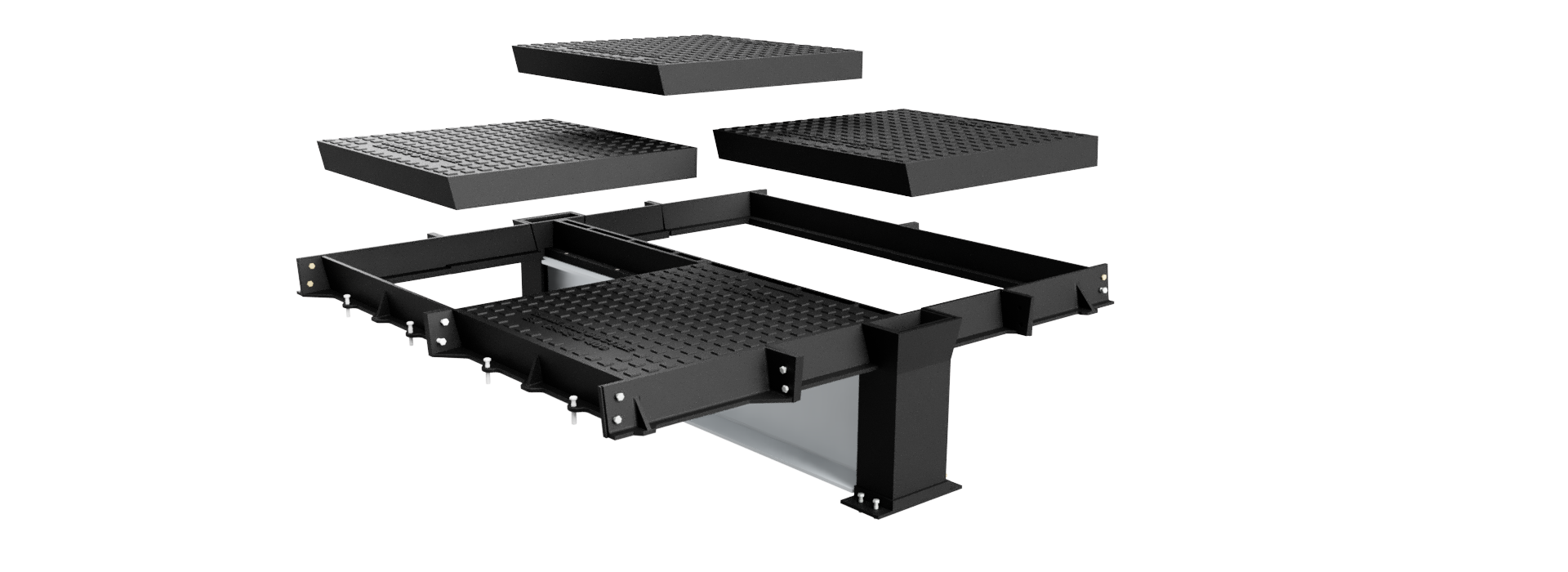
Components
| Component | Function |
|---|---|
| End frames (single and double end flange) | Form the ends of the frame. All undercut end frames are installed at one end of the pit and all drawcut end frames at the opposite end. |
| I-beam holder | End frame component incorporating the pocket that carries the removable I-beam. It must line up with the corresponding beam pocket in the slab. |
| I-beam holder cup | Locates the end of the I-beam within the holder. |
| Removable I-beam | Spans the pit and divides the opening into cover rows. It can be lifted out with suitable lifting equipment to give access to the full clear opening. |
| L angle | Sits on the I-beam to provide the cover seating along the beam line. |
| Side frames | Bolted to the end frames to complete the perimeter. |
| Covers | Numbered slide-out covers, solid top or recessed for concrete infill, each designated to one position in the frame. |
The number of side frames, mid sections, beam holders and L angles varies with the size of the unit. Refer to the supplied drawing for the exact configuration.
Undercut, Drawcut and Traffic Direction
Each run of covers has an undercut end and a drawcut end. The drawcut is identified on the cover by the edge with two keyholes, and that is the direction in which the cover slides out of the frame. Orientation matters for two reasons.
Agree the orientation on the drawing before work starts. Once the frame is concreted in, it cannot be reversed.
Before You Start
- Check the rebate dimensions and the pit clear opening against the product ordered and the supplied drawing.
- Confirm the load class suits the application. See our guide to BS EN 124 loading classes if in doubt.
- The clear opening of the frame must be equal to or larger than the clear opening of the pit. No part of the frame or packing may overhang into the opening.
- For some loadings, reinforcement is required in the rebate under the frame. Install it to the engineer’s details before setting the frame.
- Decorative edging or a paved finish may need a deeper rebate than specified, depending on the finished level.
- Use steel or other hard, incompressible packers. Timber is not suitable for the loads involved.
- Handle frame sections with care. Frames can twist and joints can be damaged if they are crushed or dropped, and machined seating faces should be kept clean and stored off the ground.
- Have to hand: the assembly drawing, lifting keys, suitable lifting equipment for beams and covers, a level or surveying equipment, string line, packers and wedges, a wrench, a rubber mallet and cover grease.
Installation Step by Step
Set out the end frames and beam holders
The frame is delivered in sections. Check that the end frame components containing the I-beam holders mate correctly with the side frame components.
- Set the end frames so each beam holder lines up with its corresponding beam pocket in the slab.
- Install all undercut end frames at one end and all drawcut end frames at the opposite end.
- Pack under the corners and under each frame joint to bring the frame up to finished floor level.
Fit the side frames and set level and square
Place the side frames into position and bolt them finger-tight to the end frames. Leaving the bolts finger-tight at this stage lets the frame settle around the covers later.
- Check that all four corners are at finished surface level, using a string line if necessary.
- Check level along each frame member and check square by measuring across the diagonals. Surveying equipment is recommended on larger units.
- Make sure neither the frame nor the packers protrude into the clear opening of the pit.
Install the I-beams and trial-fit the covers
Lower the I-beams, complete with L angles and holder cups, into the corresponding beam holders.
- Place the covers into the frame following the numbering system and the drawing, and check that the top edges of frame and covers are level with each other.
- Check every cover for diagonal rocking and adjust the packing under the frame where required. Covers must seat properly and must not be obstructed by any internal formwork.
- Once rocking, bending and tilting of the whole assembly have been ruled out, remove the covers for the next step.
Fit the covers row by row and tighten the frame
Select a row and start placing covers at the drawcut end, using the numbers on the covers and the drawing.
- Apply grease to the side faces of every cover as it goes in.
- Check each cover for rocking. If it rocks, check the rebate and seating are clean and adjust packers as required.
- As the covers go in, the frame will begin to straighten. Check all contact points: the system is designed to be extremely tight, with little tolerance, so that it stays watertight.
- The frame may need a packer or wedge to hold it tight, and this may need to stay in place during the concrete pour.
- Check that the top edges of covers and frame are level around the entire perimeter.
- Remove covers as needed to reach the finger-tight bolts, tighten them with a wrench, then refit the covers in their numbered positions.
Form up and pour the concrete
The covers stay in their numbered positions in the frame during the pour. This holds the frame to its machined geometry while the concrete sets.
- Fix internal formwork to close the gap between the underside of the frame and the chamber wall, finishing flush with the frame’s clear opening, and keep concrete out of the beam pocket cavities so the I-beams remain removable.
- Use structural-grade concrete to the engineer’s specification. For infill covers, fill the rebate gap, the frame and the infill covers in the same pour.
- Compact the concrete thoroughly so the frame is fully supported, with no voids beneath the frame flange or beam holders.
- Screed off the excess and finish the surface as required, leaving the edges of covers and frame visible. Keep concrete off the keyholes and seating joints.
Cure, strip, grease and hand over
Allow the concrete to cure fully before removing any cover. Removing covers before the concrete has cured can damage the installation.
- Remove the covers with the lifting keys provided and strip the internal formwork.
- Clean the cover and frame seating areas and grease them before reinstating each cover in its numbered position.
- Using a rubber mallet, tap down on the keyhole surround until each cover sits level with the frame.
- Refit all keyhole plugs and bolt-down fixings.
- Keep traffic off the unit until the concrete and any surrounding surfacing have fully cured.
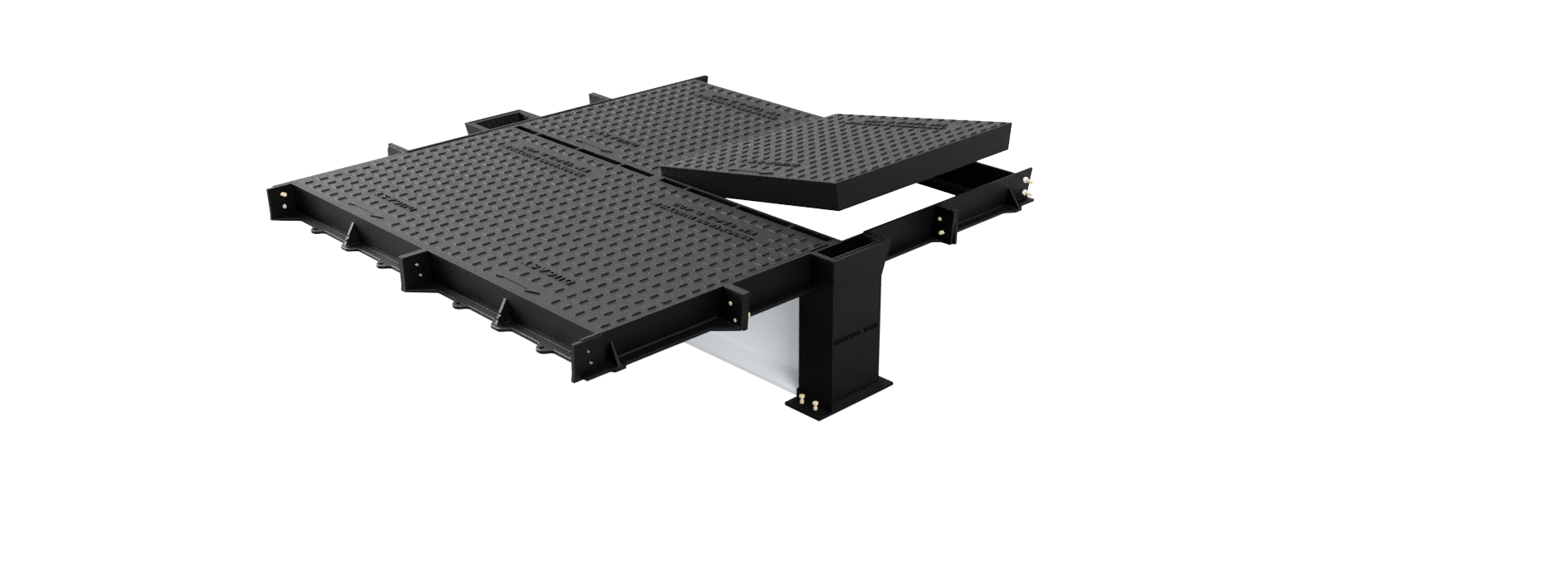
Solid Top and Concrete Infill
The frame and installation sequence are the same for both cover types. The difference lies in the surface finish.
Solid top covers are ready to traffic once the frame concrete has cured. Concrete infill covers must be filled with structural-grade concrete, fully compacted into the recesses and finished level with the cover edges. The infill is part of the load-bearing product, so it should be treated with the same care as structural concrete elsewhere on the job. Where tiles or pavers are laid in or around the unit, they should be fully restrained and bonded to the concrete bed; an epoxy mortar is recommended.
Common Installation Mistakes
| Mistake | Consequence | How to avoid it |
|---|---|---|
| Covers fitted in the wrong positions | Poor fit, rocking and a compromised seal | Follow the numbering and the drawing; mark frame and covers on every lift |
| Timber or soft packers | Packers compress or rot and the frame loses support | Use steel or other hard, incompressible packers |
| Voids under the frame | Frame flexes under load, covers rock and components can fatigue | Compact the concrete so the frame is fully supported |
| Frame overhanging the pit opening | Unsupported frame and premature failure | Frame clear opening must be equal to or larger than the pit clear opening |
| Wrong orientation to traffic | Covers can lift under traffic | Traffic flows from undercut to drawcut |
| Pouring without covers in the frame | Frame distorts and covers will not refit | Keep covers in their positions, with wedges if needed, through the pour |
| Covers lifted before the concrete cures | Damage to the frame bedding and seating | Allow full cure before removing covers |
| Dry seating faces | Water ingress, noise and covers that bind | Grease the seating and side faces every time covers are refitted |
Lifting, Refitting and Maintenance
Follow this process whenever covers are lifted, and at least once a year.
- To remove a cover, insert the lifting keys at the drawcut end, lean forward on the keys and lift the cover from the frame. Place a short section of pipe under the edge so the cover can be rolled clear of the opening.
- On multi-part units, remove covers in order and store them so they can be replaced in the same order and position. Mark the frame and covers if the markings are not clear.
- Before refitting, make sure the cover and frame seats are clean and free of all debris, then grease liberally, including every side face of each cover, to keep the joints watertight.
- Lift I-beams only with suitable lifting equipment, and plan the lift as part of the site’s manual handling and lifting arrangements.
Specification Note
For engineers writing a clause, the following wording reflects the installation requirements above and can be adapted to suit the project.
Multi-part ductile iron access cover and frame to BS EN 124-2, load class [D400 / E600 / F900], [solid top / recessed for concrete infill], slide-out covers on removable I-beam(s), pit clear opening [W] × [L] mm. Covers oriented so traffic flows from undercut to drawcut. Frame set level and square on steel packers and fully bedded on structural concrete to the engineer’s details, with covers in position during the pour. Installed in accordance with the R&B UK multi-part installation instructions and the supplied assembly drawing.
Frequently Asked Questions
Can multi-part covers be moved to a different position in the frame?
No. Covers and frames are mated individually during machining, so each cover is numbered to one position. Moving a cover can affect fit and seal. Always remove and store covers in order and refit them in the same positions.
Which way should a multi-part cover face relative to traffic?
Traffic should travel from the undercut end towards the drawcut end, which prevents covers lifting. The drawcut end is identified by the cover edge with two keyholes. Where there is an obstruction such as a wall or bollard, orient the unit so covers slide out away from it.
Should the covers be in the frame when the concrete is poured?
Yes. The covers stay in their numbered positions, with packers or wedges if needed, so the frame holds its geometry while the concrete sets. Covers should not be removed until the concrete has fully cured.
What packers should be used under a multi-part frame?
Use steel or other hard, incompressible packers under each corner and frame joint. Timber is not suitable because it can compress or degrade under load and leave the frame unsupported.
How often should multi-part covers be greased?
Clean and grease the cover and frame seats, and every side face of each cover, whenever covers are lifted and at least once a year. Grease keeps the joints watertight and lets covers slide out freely.
When is a multi-part cover needed instead of a single cover?
Multi-part systems are generally used where the pit clear opening exceeds 1200 mm in both directions. Removable I-beams divide the opening into rows of smaller covers that are easier to lift, while still giving access to the full opening when the beams are removed.
Need a Drawing or Installation Support?
Every R&B multi-part unit ships with a project-specific assembly drawing. For sizes, load classes and drawings, see our solid top multi-part access covers, or read how multi-part units are used in data centre access cover applications. For technical advice on a specific installation, get in touch with our technical team.