Specifying Access Covers for Large Openings
Most access covers are specified from a catalogue: pick the clear opening, pick the loading class, done. Large openings are different. Once a chamber needs more than about 1200 mm of clear access, the cover becomes part of the structure, and decisions about support beams, beam centres, frame depth and lifting method affect the chamber design itself. This guide covers what consulting engineers and contractors need to decide when specifying access covers for large openings, from pumping stations and storage tanks to valve chambers and cable pits.
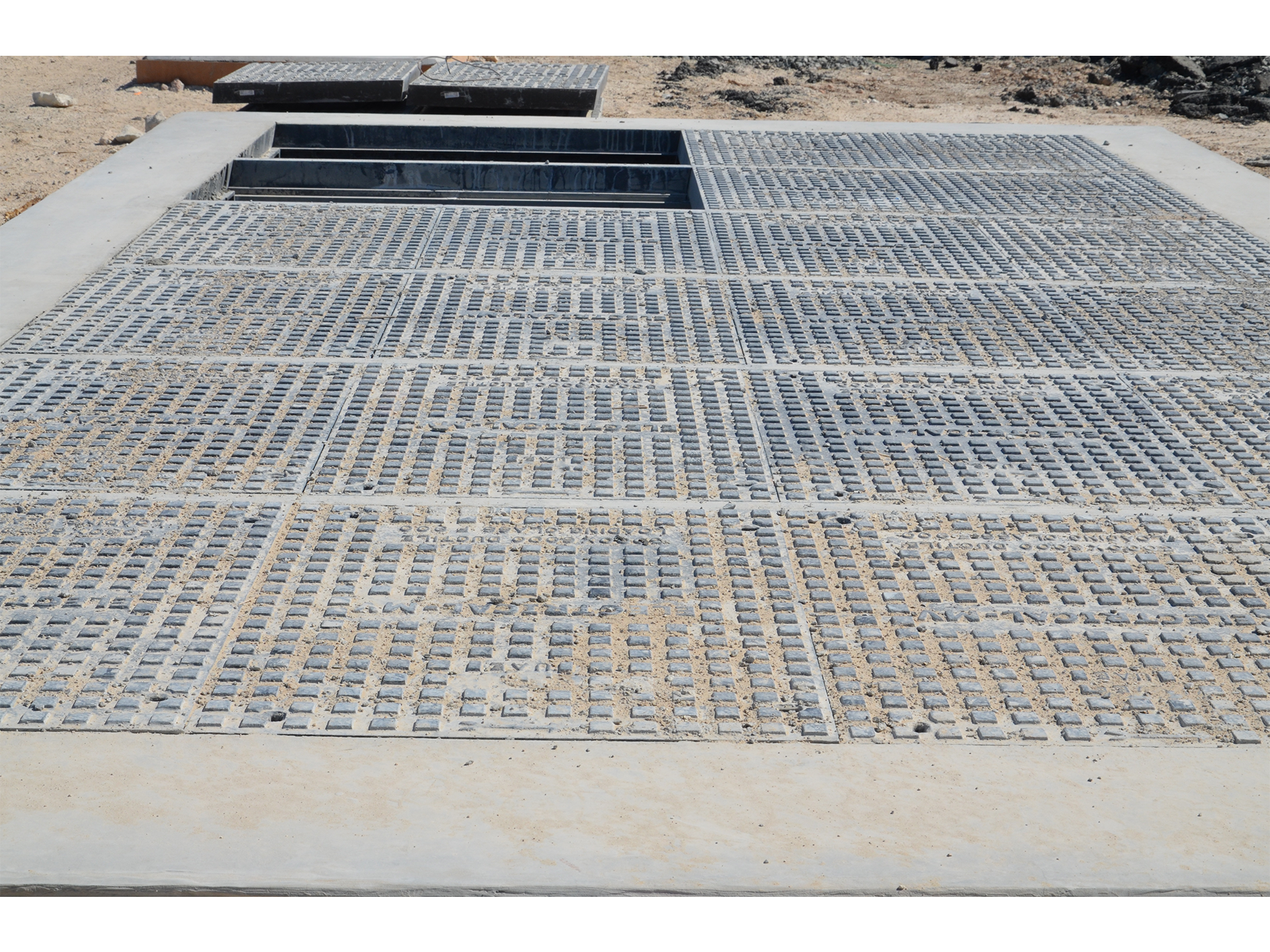
When a Single Cover Stops Being Practical
A single ductile iron cover has to carry the full test load across its whole span. As the opening grows, the cover needs more depth and more iron to stay within the deflection limits of BS EN 124, and its weight rises quickly. Long before a single cover becomes impossible to make, it becomes impossible to lift safely by hand.
That is the real limit. The Manual Handling Operations Regulations 1992 require employers to avoid hazardous lifting where they reasonably can, and a cover that needs a crane for every routine inspection is a cost the asset owner pays for decades. In trafficked areas, double triangular and two-part covers handle openings up to around 1800 x 900 mm. Beyond that, the practical answer is to divide the opening into several smaller covers supported on intermediate beams: a multi-part system.
How Multi-Part Beamed Systems Work
A multi-part system has three load-carrying elements. The frame is cast in sections that bolt together around the perimeter of the opening. Removable steel support beams span the length of the pit clear opening, between beam holders (wallboxes) at each end of the frame. The covers sit between them, each seated on the frame on one side and on a beam on the other.
Wheel loads pass from cover to beam to frame, and from the frame into the chamber walls. Because each cover only spans from the frame to a beam, or between two beams, it stays light enough to lift with keys, while the system as a whole can span 3000 mm or more. When the full opening is needed, the covers come out first, then the beams are unbolted and lifted clear.
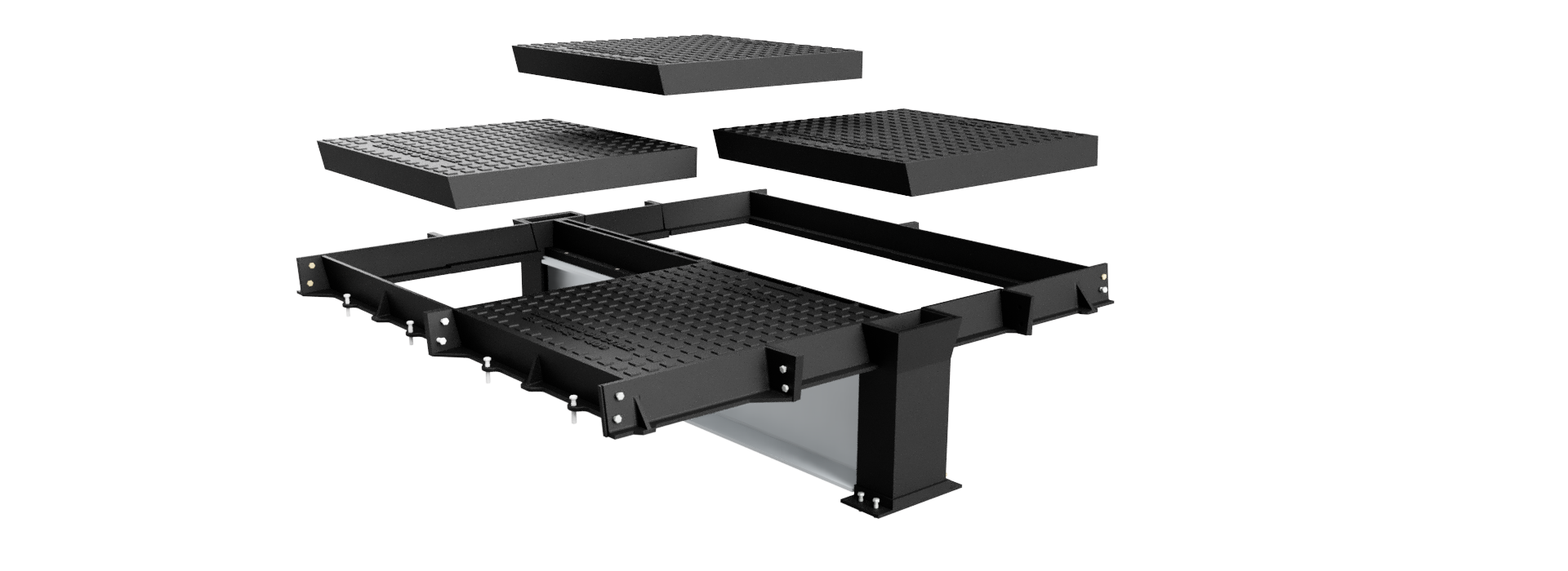
Beam size scales with the span. On our D400 range, openings up to about 2000 mm use a single 305 x 165 x 54 kg/m beam; at 3000 mm the system moves to two deeper 457 x 152 x 82 kg/m beams. Beams are hot-dip galvanised, and frame sections are coupled with stainless steel bolts so the assembly does not corrode at the joints.
See all 34 standard sizes, up to 5820 x 2400 mm, on our D400 multi-part covers and frames page.
Lift-Out, Slide-Out and Hinged Options
How the covers open matters as much as their size. There are three common approaches.
Lift-out covers are raised vertically with lifting keys. They are the simplest and most robust option and suit chambers that are opened infrequently, typically for planned maintenance.
Slide-out covers are lifted slightly and slid across the adjacent cover, so operatives move each one a short distance rather than carrying it. Machine-seated slide-out systems use machined seating faces for a close, non-rocking fit, which is why they are favoured at F900 on airfields and ports.
Hinged and spring-assisted covers open on a hinge, with torsion spring assistance reducing the effort needed. They suit chambers that are opened often, where a single operative needs regular access through one cover without disturbing the rest of the system.
Many installations combine them: a hinged or assisted cover over the ladder position for routine entry, with lift-out covers across the remainder for occasional full access.
Sizing the Opening
The clear opening should be set by what has to pass through it, not by the chamber’s internal dimensions alone. Work through these in order.
The largest item of plant. In a pumping station that is usually a pump set lifted out vertically on a guide rail; in a valve chamber, the largest valve or flow meter. Add clearance for slings and the lifting beam, then size the opening around it.
Beam centres. With the support beams in place, the space between them sets what can be lifted out without removing a beam. On an 1800 mm opening with one central beam, that is about 900 mm either side; at 2000 mm, about 1000 mm; at 3000 mm, two beams at roughly 1000 mm centres. If the item removed most often fits between the beams, routine maintenance needs only those covers lifted, and the beams stay in. Plan the beam positions around the equipment layout, not the other way round.
Personnel access. Position at least one cover directly over the ladder so operatives can enter without lifting the whole system. The usual minimum clear opening for personnel entry is 600 mm, and a larger opening makes confined space rescue easier to plan. For permanent access, a modular manhole ladder can be fitted beneath the access cover.
Future equipment. Pumps and valves get replaced with different models over a chamber’s life. Allowing some margin now is far cheaper than enlarging an opening later.
Designing the Chamber for the Cover
A large cover places specific demands on the chamber, and they need to be on the civil drawings early.
Over base. The frame’s overall footprint is larger than the clear opening, typically by about 200 to 300 mm in each direction. The chamber walls or slab must provide full bearing for it.
Beam holder depth. The beam holders sit deeper than the rest of the frame, at 420 mm on our 1800 and 2000 mm units and 580 mm at 3000 mm. The chamber needs pockets or a rebate deep enough to accommodate them.
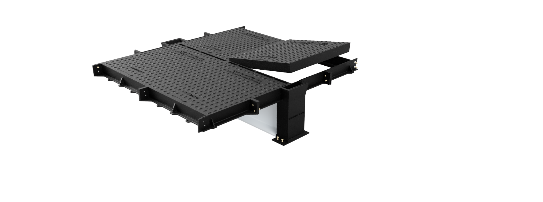
Rebate and bedding. The frame is set on a prepared wall rebate, levelled, and the rebate is then filled with concrete to lock the frame into the structure. Frame sections should be bolted together before bedding, so the assembly goes in as one unit.
Surface level and falls. Large covers in a carriageway or yard should be set flush with the finished surface. Check the frame against the surfacing make-up and any falls, because a large frame cannot be adjusted after the concrete has cured.
| Clear opening (mm) | Over base (mm) | Beam holder depth (mm) | Beams | Covers |
|---|---|---|---|---|
| 1800 x 1800 | 2100 x 1990 | 420 | 1 x 305 x 165 x 54 kg/m | 6 |
| 2000 x 2000 | 2300 x 2190 | 420 | 1 x 305 x 165 x 54 kg/m | 6 |
| 3000 x 3000 | 3270 x 3190 | 580 | 2 x 457 x 152 x 82 kg/m | 15 |
Three D400 sizes commonly specified for data centres. All are ductile iron to EN-GJS-500-7, with a 90 mm frame depth outside the beam holders. Other sizes, including long and non-square openings, are made to suit.
How Large Can a Multi-Part Cover Be?
There is no fixed upper size. Because a multi-part unit is assembled from frame sections, covers and removable support beams, it can be extended in length by adding further beams and rows of covers. We supply multi-part covers and frames in excess of 30,000 mm long.
The practical limit is the other dimension: the distance each support beam has to span between its beam holders. Our support beams span up to 3900 mm, so a multi-part unit can be up to 3900 mm wide and over 30,000 mm long. Beam section increases with that distance and with the loading class. On our D400 range, a 305 x 165 x 54 kg/m beam serves openings of around 2000 mm, while 3000 and 3500 mm openings move up to 457 x 152 x 82 kg/m beams. As the beam span grows, so does the beam depth the chamber has to accommodate, which is why very large openings are usually planned as long units of controlled width rather than as squares.
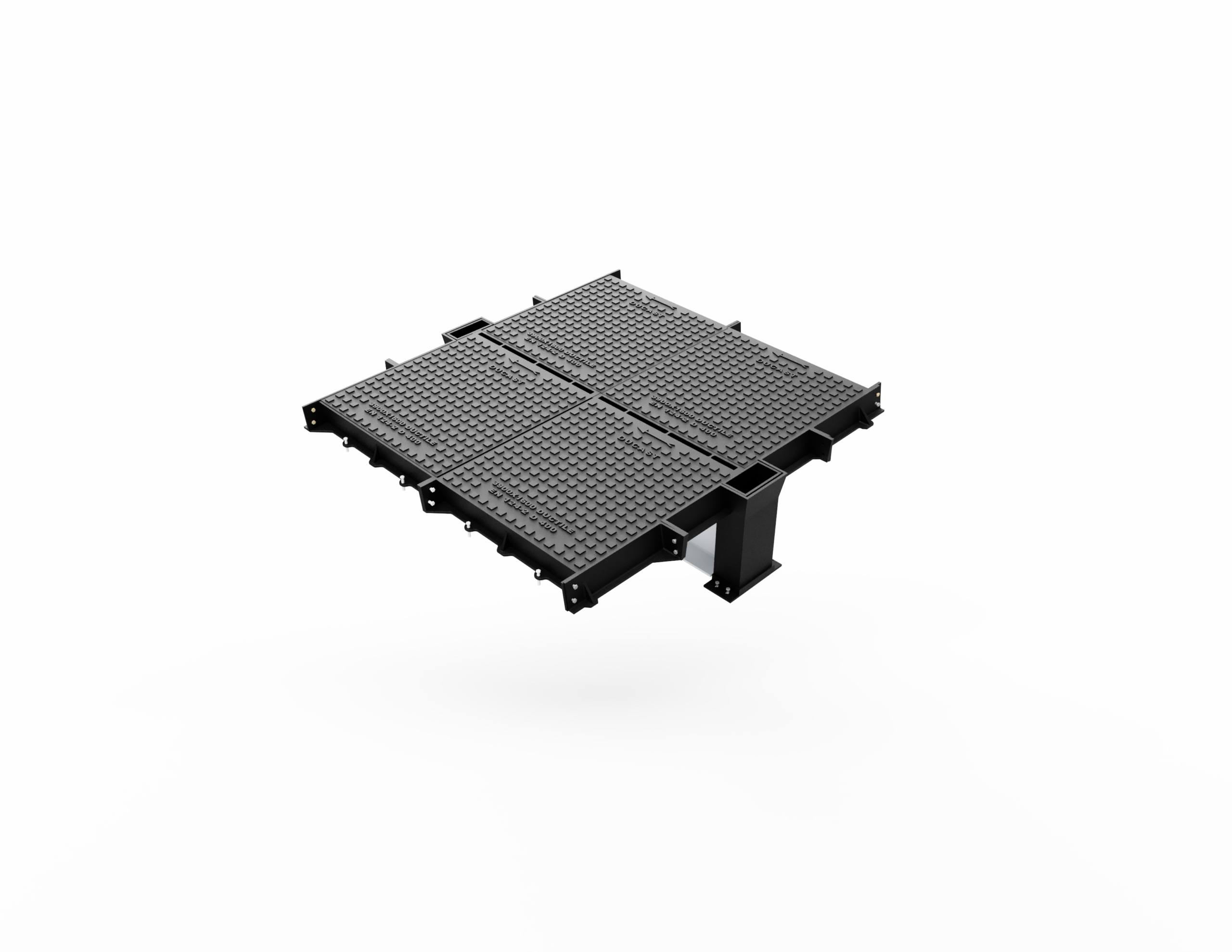
For context, the largest published standard multispan tables we are aware of also limit beam spans to 3900 mm, and stop at a pit clear opening of around 3900 mm by 5200 mm, with anything larger referred to the manufacturer. Long units are typical of cable and pipe trenches, pumping station wet wells and plant galleries, where services run the length of a building. Send us the pit layout and we will prepare a cover layout drawing showing the frame sections, beam positions and slide-out direction.
Choosing the Loading Class
The loading class follows the location, exactly as it does for a single cover. D400 is the class for carriageways, hard shoulders and parking areas used by all road vehicles. E600 covers areas of very high wheel loads such as docks and distribution yards, and F900 is specified for airport pavements and port operating areas. Our guide to BS EN 124 loading classes sets out each class in detail.
Two points are specific to large openings. First, a chamber in a service yard that only sees occasional HGVs is still a D400 location; do not specify down because traffic is light. Second, slow-moving and turning wheels, such as forklifts and straddle carriers, load a large cover harder than free-flowing traffic, which is why E600 and F900 systems are often machine-seated.
Large Openings at Data Centres
Data centres are one of the most common settings for large multi-part covers. Chilled water valve chambers, cable draw pits for incoming power and fibre, generator fuel and drainage chambers, and attenuation tanks under service yards all need wide openings in areas used by HGVs and cranes during construction, fit-out and maintenance. Clear openings of 1800 x 1800, 2000 x 2000 and 3000 x 3000 mm are among the sizes most often specified on these sites.
Because data centres are treated as critical infrastructure, the covers usually need to be lockable and tamper resistant as well as load rated. See our data centre access covers page for secure options.
Other Typical Applications
Large-opening covers appear wherever plant below ground must be installed, maintained or replaced through the surface. Common examples include pumping stations and wet wells, attenuation and storage tanks under car parks and yards, valve and meter chambers on water and wastewater networks, and transformer chambers and cable draw pits at substations.
Frequently Asked Questions
What size opening needs a multi-part cover?
In trafficked areas, single and two-part covers handle openings up to around 1800 x 900 mm. Beyond that, a multi-part system with removable beams is usually the practical choice, because it keeps each cover light enough to lift safely.
Can the beams in a multi-part cover be removed?
Yes. The beams are bolted into beam holders at each end of the frame and can be unbolted and lifted out once the covers are removed, leaving the full clear opening unobstructed.
What is the difference between lift-out and slide-out covers?
Lift-out covers are raised vertically with keys. Slide-out covers are lifted slightly and slid across the adjacent cover, so operatives move them a short distance rather than carrying them, which reduces manual handling on frequently opened chambers.
How deep does the chamber rebate need to be?
It depends on the system. Outside the beam holders, our D400 frames are 90 mm deep, but the beam holders need 420 mm on 1800 and 2000 mm openings and 580 mm at 3000 mm. Always design to the manufacturer’s drawing for the specific unit.
Are large multi-part covers available in E600 and F900?
Yes. Multi-part systems are made in D400, E600 and F900, with machine-seated slide-out versions for the heaviest loads on airfields and ports.
How long can a multi-part access cover be?
There is no fixed limit on length. Units are extended by adding further support beams and rows of covers, and we supply multi-part covers in excess of 30,000 mm long. The width is set by the support beams, which span up to 3900 mm, so the largest units are up to 3900 mm wide and over 30,000 mm long.
Need Help Specifying?
Send us the clear opening, the location and what needs to pass through it, and our Telford team will recommend a configuration and send general arrangement drawings for your design. Call 01952 580 554 or email sales@randb-uk.com, or browse the full multi-part covers and frames range.